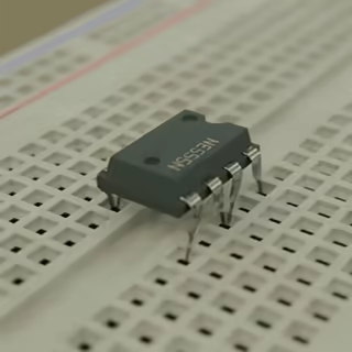

An Underground Cable Fault Detection System Using IoT is a project aimed at detecting faults in underground electrical cables, locating the exact fault point, and then sending this information over the internet for real-time monitoring. This system is highly beneficial for power companies and industrial setups where faults in underground cables can lead to power outages and system failures.
An **Underground Cable Fault Detection System Using IoT** is a project aimed at detecting faults in underground electrical cables, locating the exact fault point, and then sending this information over the internet for real-time monitoring. This system is highly beneficial for power companies and industrial setups where faults in underground cables can lead to power outages and system failures.
### **Project Overview**
The system uses a combination of hardware and IoT to detect faults in underground cables by measuring electrical parameters and detecting anomalies. Once a fault is detected, the system calculates the location of the fault in terms of distance from the base station. It then sends this data to a cloud platform or web server for easy remote monitoring.
### **Working Principle**
The core idea is based on **Ohm’s Law**: \( V = IR \). When a fault occurs in the cable, the resistance changes, causing a measurable voltage drop. By calculating this drop and knowing the cable’s parameters (like resistance per unit length), the approximate location of the fault can be estimated.
### **System Components**
1. **Microcontroller**:
- **ESP32** or **ESP8266**: Acts as both the controller and the IoT communication module due to its Wi-Fi capabilities.
2. **Sensors**:
- **Current Sensors (ACS712)**: To detect changes in current flow which indicate a fault.
- **Voltage Divider Circuit**: To measure voltage drops along the cable and help in fault location.
3. **Relays**:
- Used to simulate faults in different sections of the cable by creating intentional breaks in a prototype setup.
4. **Resistor Network**:
- Represents the cable with sections of different resistances to simulate the voltage drop when faults occur.
5. **IoT Platform**:
- Platforms like **ThingSpeak**, **Blynk**, or **Firebase** to send and display fault data.
6. **Power Supply**:
- To power the microcontroller and the sensors.
### **How It Works**
1. **Cable Simulation**:
- The cable is simulated using resistors representing segments of the cable. Relays are used to create faults at different points.
2. **Fault Detection**:
- When a fault is created (e.g., by opening a relay), the current changes in that segment. The microcontroller measures this change using the current sensor.
- The voltage drop across the resistor network is also monitored. Based on the resistance value and voltage drop, the microcontroller calculates the distance to the fault from the starting point.
3. **Data Processing**:
- The microcontroller calculates the fault distance by measuring the voltage drop and using the formula:
\[
\text{Distance} = \frac{\text{Voltage Drop} \times \text{Cable Length}}{\text{Total Voltage}}
\]
4. **IoT Communication**:
- Once a fault is detected and the distance is calculated, this information is sent to an IoT platform via Wi-Fi.
- The data is displayed on a dashboard, showing real-time updates of the fault location.
### **Circuit Diagram**
1. Connect the **current sensor** (e.g., ACS712) in series with the cable simulation.
2. Set up a **voltage divider circuit** with resistors in sections.
3. Use **relays** to simulate faults by disconnecting certain segments.
### **Sample Code**
This code reads the current sensor and calculates the fault distance, then sends the data to ThingSpeak.
#### **Arduino Code for ESP32 or ESP8266**
```cpp
#include